Overview
The dot-raw updater plugin takes results from SAInt and writes them to a .raw file. It extracts electrical network data from SAInt network and scenario files and updates corresponding properties in dot-raw files.
Versions Compatible with SAInt 3.8
- v0.3.3 (92.7 MB)
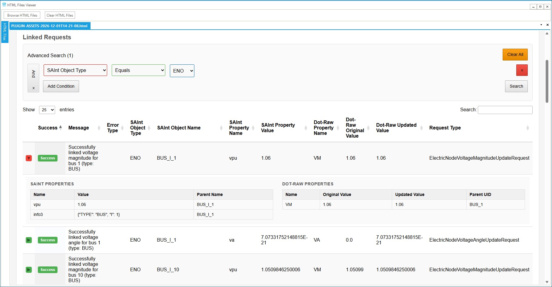
Screenshot:
Inputs
Required Files
SAInt Network File (.enet): The SAInt electric network file containing the electrical network topology and component definitions. This file defines the structure of the power system including buses, generators, loads, branches, transformers, and shunts. Default: Uses the currently open network file in SAInt.
SAInt Scenario File (.esce): The SAInt electric scenario file containing the operational data and state information for the electrical components. This includes power flows, voltage levels, generator outputs, load demands, and component states. Default: Uses the currently open scenario file in SAInt.
dot-raw File (.raw): The dot-raw file that will be updated with the SAInt data. This is the target file that contains the electrical network data in dot-raw format.
Output Settings
Output Directory: The folder where the updated dot-raw file will be saved. The original file is copied to this location and updated with a “_updated” suffix. Default: The PluginOutput folder in your SAInt documents directory.
Custom Report Filename (Optional): Optional custom name for the generated HTML report file. If not specified, a default report filename (based on the output folder name) will be used.
Custom Results JSON Filename (Optional): Optional custom name for the results JSON file. If not specified, defaults to results.json.
System Settings
Use Scenario Inputs: When enabled, the updater uses scenario input properties (e.g., pset, qset, vmset) from the SAInt scenario file instead of output properties (e.g., p, q, info3). This mode is primarily used when the simulation cannot be solved and output data is unavailable. Default: False (uses output data).
Update PV/WIND/ESTR voltage setpoint with remote bus voltage: When enabled, reactive-regulated generators (PV, WIND, ESTR) with a valid IREG property will use the voltage from the remote bus specified by IREG instead of the generator’s VMSET or parent node VPU. The IREG property must contain a valid bus number (not None, NaN, or 0), and exactly one electric node must exist with that bus number in the Info3[“I”] property. Default: False (uses standard VMSET/parent node logic).
SAInt API DLL Path: Path to the SAInt API DLL file. Default: Automatically uses the SAInt-API.dll from your SAInt installation directory (typically C:\Program Files\encoord\SAInt-v3\SAInt-API.dll).
Logging Level: Controls the verbosity of logging output. Options: Debug, Info, Warning, Error, Critical. Default: Info
What Properties Are Updated
The dot-raw updater can update the following electrical properties in dot-raw files. The source of these values depends on whether Use Scenario Inputs is enabled:
- Scenario Outputs (default): Uses SAInt output properties from simulation results (e.g.,
p,q,info3) - Scenario Inputs: Uses SAInt scenario input properties (e.g.,
pset,qset,vmset) to apply scenario configurations before simulation
Scenario Outputs
Generator Properties
- Active Power (pg): Generator active power output in MW (from
pproperty) - Reactive Power (qg): Generator reactive power output in MVAR (from
qproperty) - Voltage Setpoint (vs): Generator voltage setpoint in per-unit. The source of this value depends on the generator type and configuration:
- Remote Node VPU (IREG): For reactive-regulated generators (PV, WIND, ESTR) when Update PV/WIND/ESTR voltage setpoint with remote bus voltage is enabled and IREG is valid (not None, NaN, or 0), the voltage setpoint is linked from the remote electric node’s
VPUproperty. The remote node is identified by matching the generator’s IREG property value to the electric node’s Info3[“I”] property. This takes precedence over VMSET and parent node logic when enabled and IREG is valid. - Direct VMSET: Linked from the generator’s
VMSETproperty when:- For voltage-regulated generators (PV, WIND, ESTR): when
VMSETis available and not NaN, and remote node logic is not used - For reactive-regulated generators (XGEN, FGEN, HGEN, EPS, PHSTR): when
QSETis NaN andVMSETis available
- For voltage-regulated generators (PV, WIND, ESTR): when
- Remote Node VPU (QSET): For reactive-regulated generators with a remote node configured, the voltage setpoint is linked from the remote node’s
VPUproperty whenQSETis not NaN (legacy behavior, applies when IREG logic is not used) - Parent Node VPU: Linked from the generator’s parent electric node’s
VPUproperty when:- For voltage-regulated generators: when
VMSETis NaN - For reactive-regulated generators: when
QSETis not NaN and no remote node is configured (or IREG is invalid/unavailable)
- For voltage-regulated generators: when
- Remote Node VPU (IREG): For reactive-regulated generators (PV, WIND, ESTR) when Update PV/WIND/ESTR voltage setpoint with remote bus voltage is enabled and IREG is valid (not None, NaN, or 0), the voltage setpoint is linked from the remote electric node’s
- State (status): Generator operational state (ON/OFF → 1/0)
Note: SAInt generator requests automatically skip HVDC inverters/rectifiers (TYPE = “TWO-TERMINAL DC”) and VSC converters (TYPE = “VSC DC LINE”) since they are handled by their respective line requests.
Load Properties
- Active Power (pl): Load active power demand in MW (from
pproperty) - Reactive Power (ql): Load reactive power demand in MVAR (from
qproperty) - State (status): Load operational state (ON/OFF → 1/0)
Bus Properties
- Voltage Magnitude (vm): Bus voltage magnitude in per-unit (from
vpuproperty) - Voltage Angle (va): Bus voltage angle in degrees (from
vaproperty)
Star Bus Properties
- Voltage Magnitude (vmstar): Star bus voltage magnitude in per-unit (from
vpuproperty). Maps to transformer VMSTAR property. - Voltage Angle (anstar): Star bus voltage angle in degrees (from
vaproperty). Maps to transformer ANSTAR property.
The Star Bus update logic works as follows:
- The SAInt electric node must be a STAR_BUS type node
- The updater finds three transformers (I, J, K) connected to the STAR_BUS node via their
ToNameproperty matching the node name - Each transformer must have an Info3 property containing:
- Bus number (I) for transformers I, J, and K
- Circuit identifier (CKT) from transformer I
- The updater extracts bus numbers I, J, K and circuit CKT from the three transformers
- The corresponding dot-raw transformer is located using these identifiers
- The STAR_BUS node’s VPU value is mapped to the transformer’s VMSTAR property
- The STAR_BUS node’s VA value is mapped to the transformer’s ANSTAR property
Requirements:
- Exactly three transformers must have
ToNamematching the STAR_BUS node name - Transformer I must have a name containing “TRANSFORMER_I” (case-insensitive)
- Transformer J must have a name containing “TRANSFORMER_J” (case-insensitive)
- Transformer K must have a name containing “TRANSFORMER_K” (case-insensitive)
- The dot-raw transformer must have VMSTAR property (for voltage magnitude) or ANSTAR property (for voltage angle)
Branch Properties (AC Lines)
- State (status): AC transmission line operational state (ON/OFF → 1/0)
- Dummy Transformers: If a line has an associated dummy transformer (named
DUMMY_TRF_BRANCH_I_{bus_i}_J_{bus_j}_CKT_{ckt}), the line’s state update uses the dummy transformer’s state value instead of the line’s own state. If no dummy transformer exists or the dummy transformer has no state property, the line’s own state is used.
- Dummy Transformers: If a line has an associated dummy transformer (named
Note: Line state requests skip HVDC two-terminal DC lines, VSC DC lines, and SYSTEM SWITCHING DEVICE lines. System switching devices are skipped because they are system-level components that require different handling than standard AC transmission lines.
Two-Terminal DC (HVDC) Properties
- Active Power (setvl): HVDC line set value calculated from SAInt rectifier/inverter generators based on control mode:
- MDC = 1 (Power): If existing SETVL >= 0, uses
abs(rectifier.P); otherwise uses-1 * inverter.P - MDC = 2 (Current): Uses
(abs(rectifier.P) / VSCHD) * 1000to calculate current in amps - Other MDC values are skipped (no update applied)
- MDC = 1 (Power): If existing SETVL >= 0, uses
VSC DC Line Properties
- DC Setpoint 1 (dcset1): Converter 1 DC setpoint, updated when TYPE1 = 2 (power control mode)
- DC Setpoint 2 (dcset2): Converter 2 DC setpoint, updated when TYPE2 = 2 (power control mode)
The VSC DC line update logic works as follows:
- The SAInt Line object’s Info3 property identifies the VSC DC line by NAME
- The updater finds corresponding SAInt converter generators (names containing “CONVERTER1” and “CONVERTER2”) grouped by the VSC line NAME
- Based on the dot-raw TYPE1/TYPE2 control mode values:
- TYPE1 = 2: Sets
DCSET1 = converter1.P(active power from Converter 1) - TYPE2 = 2: Sets
DCSET2 = converter2.P(active power from Converter 2) - If neither TYPE1 nor TYPE2 equals 2, the update is skipped with a linking error
- TYPE1 = 2: Sets
Transformer Properties
- State (status): Transformer operational state (ON/OFF → 1/0)
- Dummy Transformers: Transformers with names starting with
DUMMY_are skipped by the transformer state update logic. These dummy transformers are handled by the line state update logic instead, where their state values are mapped to the originating line’s state. - STAR Transformers: Transformers with names containing “STAR” (case-insensitive) are automatically skipped. These are special transformer types that require different handling and will appear in the report with a warning message.
- Dummy Transformers: Transformers with names starting with
Shunt Properties
- Fixed Shunt State (status): Fixed shunt operational state (ON/OFF → 1/0)
- Switched Shunt State (status): Switched shunt operational state (ON/OFF → 1/0)
- Switched Shunt Susceptance Setpoint (binit): Switched shunt susceptance setpoint in per-unit (from
bsetproperty). Only applies to switched shunts; fixed shunts are automatically skipped.
The switched shunt susceptance setpoint update logic works as follows:
- The SAInt shunt must have a
bsetproperty containing the susceptance setpoint value - The shunt’s
info3property must containTYPE = "SWITCHED SHUNT"and bus numberI - The updater locates the corresponding switched shunt in the dot-raw file using the bus number from
info3 - The
BSETvalue from SAInt is mapped to theBINITproperty in the dot-raw switched shunt - Fixed shunts (non-switched) are automatically skipped with a success message
Note: Shunts (both fixed and switched) with names containing “GIBI” or “GJBJ” (case-insensitive) are automatically skipped. These are special shunt types that require different handling and will appear in the report with a warning message.
Scenario Inputs
Generator Properties
- Active Power (pg): Generator active power setpoint in MW (from
psetproperty) - Reactive Power (qg): Generator reactive power setpoint in MVAR (from
info3property for TYPE=LOAD generators) - Voltage Setpoint (vs): Generator voltage setpoint in per-unit (from
vmsetproperty). LOAD type generators are automatically skipped. - State (status): Generator operational state (ON/OFF → 1/0)
Note: SAInt generator requests automatically skip HVDC inverters/rectifiers (TYPE = “TWO-TERMINAL DC”) and VSC converters (TYPE = “VSC DC LINE”) since they are handled by their respective line requests.
Load Properties
- Active Power (pl): Load active power setpoint in MW (from
psetproperty) - Reactive Power (ql): Load reactive power setpoint in MVAR (from
qsetproperty, or pwf ratio calculation frompset) - State (status): Load operational state (ON/OFF → 1/0)
Branch Properties (AC Lines)
- State (status): AC transmission line operational state (ON/OFF → 1/0)
- Dummy Transformers: If a line has an associated dummy transformer (named
DUMMY_TRF_BRANCH_I_{bus_i}_J_{bus_j}_CKT_{ckt}), the line’s state update uses the dummy transformer’s state value instead of the line’s own state. If no dummy transformer exists or the dummy transformer has no state property, the line’s own state is used.
- Dummy Transformers: If a line has an associated dummy transformer (named
Note: Line state requests skip HVDC two-terminal DC lines, VSC DC lines, and SYSTEM SWITCHING DEVICE lines. System switching devices are skipped because they are system-level components that require different handling than standard AC transmission lines.
Two-Terminal DC (HVDC) Properties
- Uses the same logic as Scenario Outputs mode, but reads from scenario input data of related device
pset
VSC DC Line Properties
- Uses the same logic as Scenario Outputs mode, but reads from scenario input data of related device
pset
Transformer Properties
- State (status): Transformer operational state (ON/OFF → 1/0)
- Dummy Transformers: Transformers with names starting with
DUMMY_are skipped by the transformer state update logic. These dummy transformers are handled by the line state update logic instead, where their state values are mapped to the originating line’s state. - STAR Transformers: Transformers with names containing “STAR” (case-insensitive) are automatically skipped. These are special transformer types that require different handling and will appear in the report with a warning message.
- Dummy Transformers: Transformers with names starting with
Shunt Properties
- Fixed Shunt State (status): Fixed shunt operational state (ON/OFF → 1/0)
- Switched Shunt State (status): Switched shunt operational state (ON/OFF → 1/0)
- Switched Shunt Susceptance Setpoint (binit): Switched shunt susceptance setpoint in per-unit (from
bsetproperty). Only applies to switched shunts; fixed shunts are automatically skipped.
The switched shunt susceptance setpoint update logic works as follows:
- The SAInt shunt must have a
bsetproperty containing the susceptance setpoint value - The shunt’s
info3property must containTYPE = "SWITCHED SHUNT"and bus numberI - The updater locates the corresponding switched shunt in the dot-raw file using the bus number from
info3 - The
BSETvalue from SAInt is mapped to theBINITproperty in the dot-raw switched shunt - Fixed shunts (non-switched) are automatically skipped with a success message
Note: Shunts (both fixed and switched) with names containing “GIBI” or “GJBJ” (case-insensitive) are automatically skipped. These are special shunt types that require different handling and will appear in the report with a warning message.
Info3 Property Mapping
The updater maps SAInt objects to dot-raw properties using the Info3 property on each SAInt object. This property contains a JSON string with the dot-raw object type and identifying fields. The required format for each object type is:
| SAInt Object | Info3 Format | Example |
|---|---|---|
| Electric Node | {"TYPE": "BUS", "I": <bus_number>} |
{"TYPE": "BUS", "I": 1} |
| Electric Demand | {"TYPE": "LOAD", "I": <bus_number>, "ID": "<load_id>"} |
{"TYPE": "LOAD", "I": 2, "ID": "1"} |
| Generator | {"TYPE": "GENERATOR", "I": <bus_number>, "ID": "<generator_id>"} |
{"TYPE": "GENERATOR", "I": 1, "ID": "1"} |
| Line (AC Branch) | {"TYPE": "BRANCH", "I": <from_bus>, "J": <to_bus>, "CKT": "<circuit>"} |
{"TYPE": "BRANCH", "I": 1, "J": 2, "CKT": "1"} |
| Line (HVDC) | {"TYPE": "TWO-TERMINAL DC", "I": <dc_line_number>} |
{"TYPE": "TWO-TERMINAL DC", "I": 1} |
| Line (VSC DC) | {"TYPE": "VSC DC LINE", "NAME": "<vsc_line_name>"} |
{"TYPE": "VSC DC LINE", "NAME": "CSC-VSC-1"} |
| Transformer | {"TYPE": "TRANSFORMER", "I": <bus_i>, "J": <bus_j>, "K": <bus_k>, "CKT": "<circuit>"} |
{"TYPE": "TRANSFORMER", "I": 1, "J": 2, "K": 0, "CKT": "1"} |
| Shunt (Fixed) | {"TYPE": "FIXED SHUNT", "I": <bus_number>, "ID": "<shunt_id>"} |
{"TYPE": "FIXED SHUNT", "I": 5, "ID": "1"} |
| Shunt (Switched) | {"TYPE": "SWITCHED SHUNT", "I": <bus_number>} |
{"TYPE": "SWITCHED SHUNT", "I": 5} |
Note: For HVDC lines, the rectifier and inverter generators must also have Info3 with TYPE = "TWO-TERMINAL DC" and the same I value as the line, plus PGMAXDEF = 0 (rectifier) or PDMAXDEF = 0 (inverter) to identify their role.
Note: For VSC DC lines, the converter generators must also have Info3 with TYPE = "VSC DC LINE" and the same NAME value as the line. Converter generators are identified by their SAInt object name containing “CONVERTER1” or “CONVERTER2”.
Naming Conventions
The updater uses specific naming conventions to identify and link special objects in SAInt data. These conventions allow the updater to handle special cases and relationships between objects.
Dummy Transformers
Dummy transformers are special transformer objects created when a line connects nodes of unequal base voltages. They represent line state information and follow a specific naming convention that allows them to be automatically associated with their originating line:
Naming Pattern: DUMMY_TRF_BRANCH_I_{bus_i}_J_{bus_j}_CKT_{ckt}
Where:
{bus_i}is the from bus number{bus_j}is the to bus number{ckt}is the circuit identifier
Example: DUMMY_TRF_BRANCH_I_119_J_1190_CKT_1 represents a dummy transformer associated with a line from bus 119 to bus 1190, circuit 1.
Behavior:
- Dummy transformers are automatically detected during line state updates
- The dummy transformer’s state value is used to update the associated line’s state
- Dummy transformers are skipped by the transformer state update logic
- If a dummy transformer exists but has no state property, the line’s own state is used as a fallback
VSC Converter Generators
VSC converter generators are special generator objects that represent the converters at each end of a VSC DC line. They are identified by their SAInt object name containing specific keywords that indicate their role:
Naming Requirements:
- Converter 1 generators must have “CONVERTER1” (case-insensitive) in their SAInt object name
- Converter 2 generators must have “CONVERTER2” (case-insensitive) in their SAInt object name
Info3 Requirements:
- Both converters must have Info3 with
TYPE = "VSC DC LINE"and the sameNAMEvalue as the VSC DC line they belong to
Example: For a VSC DC line with NAME = "CSC-VSC-1":
- Converter 1 generator might be named:
"CSC-VSC-1_CONVERTER1"or"VSC_CONVERTER1_CSC-VSC-1" - Converter 2 generator might be named:
"CSC-VSC-1_CONVERTER2"or"VSC_CONVERTER2_CSC-VSC-1" - Both must have Info3:
{"TYPE": "VSC DC LINE", "NAME": "CSC-VSC-1"}
Behavior:
- VSC converter generators are automatically grouped by their VSC line NAME during data extraction
- The updater uses the converter generators’ active power (P) values to update the VSC DC line’s DCSET1/DCSET2 properties
- VSC converter generators are automatically skipped by generator update requests (active power, reactive power, voltage setpoint, state) since they are handled by the VSC DC line request
STAR_BUS Transformers
STAR_BUS transformers are special transformer objects used to represent three-winding transformers connected to a STAR_BUS electric node. They are identified through a three-transformer system and their relationship to the STAR_BUS node:
Naming Requirements:
- Transformer I must have “TRANSFORMER_I” (case-insensitive) in its SAInt object name
- Transformer J must have “TRANSFORMER_J” (case-insensitive) in its SAInt object name
- Transformer K must have “TRANSFORMER_K” (case-insensitive) in its SAInt object name
Property Requirements:
- All three transformers must have a
ToNameproperty matching the STAR_BUS electric node name - Each transformer must have an Info3 property containing:
- Bus number (I) for transformers I, J, and K
- Circuit identifier (CKT) from transformer I (used for all three)
Info3 Format:
- Transformer I:
{"I": <bus_i>, "CKT": "<circuit>"} - Transformer J:
{"I": <bus_j>, "CKT": "<circuit>"} - Transformer K:
{"I": <bus_k>, "CKT": "<circuit>"}
Example: For a STAR_BUS node named “STAR_BUS_NODE”:
- Transformer I might be named:
"TRANSFORMER_I_100"withToName = "STAR_BUS_NODE"and Info3:{"I": 100, "CKT": "1"} - Transformer J might be named:
"TRANSFORMER_J_200"withToName = "STAR_BUS_NODE"and Info3:{"I": 200, "CKT": "1"} - Transformer K might be named:
"TRANSFORMER_K_300"withToName = "STAR_BUS_NODE"and Info3:{"I": 300, "CKT": "1"}
Behavior:
- STAR_BUS transformers are automatically indexed by their
ToNameproperty during SAInt data extraction - The updater uses the STAR_BUS electric node’s VPU value to update the corresponding dot-raw transformer’s VMSTAR property
- The updater uses the STAR_BUS electric node’s VA value to update the corresponding dot-raw transformer’s ANSTAR property
- The dot-raw transformer is identified by combining bus numbers I, J, K and circuit CKT from the three SAInt transformers
- Exactly three transformers must be found with matching
ToName; otherwise, the update fails with a linking error
Output
The plugin generates the following files in the output directory:
-
Updated dot-raw file: Copy of the original file with SAInt data applied. The filename has a “_updated” suffix added to the original filename.
-
Results JSON file: A JSON file containing all update requests, link results, and file update results. This provides machine-readable access to all processing details. Default filename:
results.json. -
HTML Report: A detailed HTML report summarizing all updates performed, including statistics, linked requests, and any errors or warnings. The default filename is based on the output folder name with a
.htmlextension, or uses the custom report filename if specified.
Scenario Inputs Mode
When Use Scenario Inputs is enabled, the updater operates in Scenario Inputs Mode, which uses scenario input properties instead of output properties. This mode is primarily used when the simulation cannot be solved, allowing you to apply scenario input configurations directly to the dot-raw file even when output data is unavailable.
Key Differences Between Modes
| Property | Scenario Outputs Source | Scenario Inputs Source |
|---|---|---|
| Generator Active Power | p (output) |
pset (input setpoint) |
| Generator Reactive Power (reference property only) | q (output) |
no update |
| Generator Voltage Setpoint | vmset or info3 (complex logic) |
vmset (skips LOAD types) |
| Load Active Power | p (output) |
pset (input setpoint) |
| Load Reactive Power | q (output) |
qset (input setpoint) or pwf ratio calculation from pset |
| HVDC Active Power | Calculated from rectifier/inverter p |
Calculated from rectifier/inverter pset |
| VSC DC Active Power | From converter generator p |
From converter generator pset |
| Shunt Susceptance Setpoint | bset (output) |
bset (input setpoint) |
When to Use Each Mode
-
Scenario Outputs (default): Use when you want to update dot-raw files with results from a completed SAInt simulation. This is the typical workflow for post-processing simulation results.
-
Scenario Inputs: Use when the simulation cannot be solved and output data is unavailable. This mode allows you to apply scenario input configurations directly to the dot-raw file using the scenario’s input properties (e.g.,
pset,qset,vmset) instead of waiting for simulation results.
Changelog
v0.3.3
Features:
- Shunt Susceptance Setpoint Updates - Support for updating switched shunt BINIT properties from SAInt shunt BSET values
v0.3.2
Features:
- Star Node Voltage Magnitude/Angle Updates - Support for updating transformer VMSTAR and ANSTAR properties from STAR_BUS electric nodes
- Option to update PV/WIND/ESTR generator voltage setpoints using remote bus voltage via IREG property
v0.3.1
Features:
- Initial MVP release
- Option to update dot-raw with SAInt ACPF Inputs (scenario inputs mode)
- Support for HVDC updating
- Support for VSC updating
- Use Info3 property for object linking
- Use GUI parameter to prepopulate form
- Handling for negative loads
- Logic for VSET/QSET of generators
- State of dummy transformers maps to originating line
- Option to update PV/WIND/ESTR generator voltage setpoints using remote bus voltage via IREG property