Overview
The Nodal to Zonal Converter plugin converts a detailed nodal network model into a simplified zonal network model in SAInt. It aggregates multiple nodes within each zone into a single reference node and replaces inter-zone branches with zonal interties that represent transfer capacities as derived from shift factor calculations and equivalent impedances between zones.
Versions Compatible with SAInt 3.8
- v0.1.3 (33.3 MB)
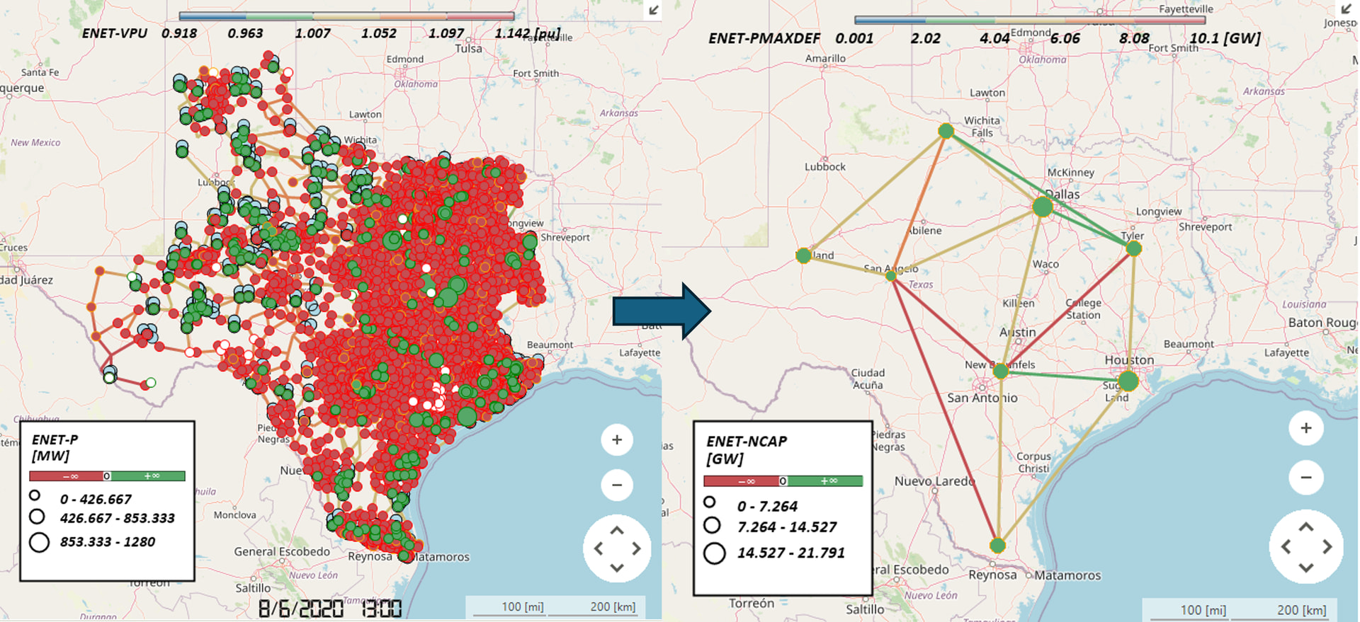
Screenshot:
Inputs
Required Files
SAInt Network File (.enet): The SAInt electric network file containing the nodal network topology. This file must include:
- Electric nodes (ENO) with zone assignments
- Electric branches (EBR) connecting nodes
- Zone objects (EZN) with reference node specifications
- External objects (EXT)
Output Settings
Output Directory: The folder where the converted zonal network file will be saved. The original network file is first copied to this location, then the copy is modified in-place to create the zonal network. The original file is never modified.
Custom Report Filename (Optional): Optional custom name for the generated HTML report file. If not specified, a default report filename will be used (output folder name + “.html”). If provided without extension, “.html” will be automatically appended.
Custom Nodal Network Filename (Optional): Optional custom name for the output zonal network file. If not specified, the original filename will be used with a “_ZONAL” suffix (e.g., “network.enet” → “network_ZONAL.enet”). If provided without extension, “.enet” will be automatically appended. This file contains the converted zonal network.
Update Records CSV Filename (Optional, API only): Optional custom name for the update records CSV file. If not specified, defaults to “update_records.csv”. Note: This option is only available when using the API directly (e.g., from_files() function). The CLI and plugin UI interfaces use the default filename.
System Settings
SAInt API DLL Path: Path to the SAInt API DLL file. Default: C:\Program Files\encoord\SAInt-v3\SAInt-API.dll
Logging Level: Controls the verbosity of logging output. Options: Debug, Info, Warning, Error, Critical
Zone Configuration Requirements
CRITICAL: Each SAInt Zone object (EZN) must have the name of its reference node stored in the ReferenceNodeName property. The plugin reads this value to identify which node in each zone serves as the reference node for the zonal model.
- The reference node name must exactly match the name of an existing electric node (ENO) in the network
- The reference node must belong to the same zone as specified in the zone object
- If a zone’s ReferenceNodeName property does not contain a valid node name, the zone will be skipped with a warning
Computation Logic
The conversion process follows these steps:
1. Generate SAInt Object Information
The plugin extracts all network objects from the SAInt network file:
- Electric Nodes (ENO): Extracts node names and zone assignments
- Electric Branches (EBR): Extracts branch names, object types (ObjType), endpoints, in-service status, PMAXDEF (maximum power transfer capacity), and XXDEF (impedance). Both PMAXDEF and XXDEF are parsed to handle infinity representations (e.g., “+Inf”, “INF”)
- Zones (EZN): Extracts zone names and reference node names from the ReferenceNodeName property
- Externals (EXT): Extracts external object names and their referenced nodes
Reference nodes are identified by matching zone ReferenceNodeName property values to node names, and these nodes are marked as reference nodes.
2. Create Zonal Interties
The plugin identifies branches that connect different zones and groups them into zonal interties:
- Branch Grouping: All branches connecting two different zones are grouped by zone pair (from_zone, to_zone)
- Direction Determination: For each zone pair, the plugin applies a majority rule:
- If more branches flow from Zone A to Zone B than from Zone B to Zone A, the intertie direction is A → B
- If the counts are equal, the original direction (A → B) is preserved
- Intertie Creation: A zonal intertie object is created for each unique zone pair, containing all branches that connect those zones
- Naming: Zonal interties are named using the pattern
ZONAL_INTERTIE_{from_zone}_{to_zone}
Branches that connect nodes within the same zone are excluded from intertie creation.
3. Compute Zonal Intertie Capacity
For each zonal intertie, the plugin calculates the aggregate transfer capacity using power flow analysis:
-
Injection Shift Factor (ISF) Calculation: For each in-service branch in the intertie, the plugin computes the ISF using the SAInt API:
- ISF measures the sensitivity of branch flow to power injection at the from-zone reference node
- The reference node of the to-zone is used as the reference node for the ISF calculation
- Formula:
isf('EBR.{branch_name}', 'ENO.{from_node}', referenceNode='ENO.{to_node}')
-
Capacity Ratio Calculation: For each in-service branch, the capacity ratio is computed as:
- If
ISF = 0, the capacity ratio is set to infinity (representing an unconstrained branch) - Otherwise,
capacity_ratio = |PMAXDEF / ISF| - This represents the maximum power that can be transferred through the intertie before the branch reaches its PMAXDEF limit
- If
-
Sum of Absolute ISF Values: The sum of absolute ISF values across all in-service branches is computed:
sum_abs_isf = Σ|ISF_i|for all in-service branchesi- This represents the aggregate sensitivity of the intertie to power injection
-
Zonal Intertie Capacity Calculation: The zonal intertie capacity is computed as:
- If no branches are in-service, the capacity is set to 0.0
- If the minimum capacity ratio is infinity and the sum of absolute ISF values is 0.0, the capacity is set to 0.0
- Otherwise,
zonal_intertie_capacity = min(all_branch_capacity_ratios) × sum_abs_isf - The minimum capacity ratio ensures the intertie capacity respects the most limiting branch constraint
- The multiplication by the sum of absolute ISF values accounts for the aggregate flow distribution across all parallel branches
This approach ensures that the zonal intertie capacity accurately represents the aggregate transfer capability between zones while respecting individual branch constraints.
4. Compute Zonal Intertie Impedance
For each zonal intertie, the plugin calculates the proportionally equivalent impedance using the parallel impedance formula:
-
Impedance Parsing: The plugin extracts
XXDEFvalues from branches, parsing them similarly toPMAXDEFto handle infinity representations (e.g., “+Inf”, “INF”) -
Parallel Impedance Calculation: For each zonal intertie composed of multiple nodal branches, the equivalent impedance is computed as:
- Formula:
XXDEF_zonal = 1 / Σ(1/XXDEF_nodal_i)for all nodal branchesi - This is mathematically equivalent to calculating the equivalent impedance of parallel resistors
- The sum is taken over all valid (positive) branch impedances
- Formula:
-
Edge Case Handling:
- Branches with zero or negative
XXDEFvalues are skipped (representing invalid or out-of-service branches) - If no branches have valid impedance values, the zonal intertie impedance is set to
0.0
- Branches with zero or negative
-
Result: The computed impedance value is stored in the
xxdefattribute of eachZonalIntertieInformationobject and will be applied to the zonal intertie line in the network.
This approach ensures that the zonal intertie impedance accurately represents the combined electrical behavior of the underlying parallel branches, maintaining the correct electrical characteristics in the simplified zonal model.
5. Update Network
The plugin performs the following network modifications to create the zonal model:
Create Zonal Intertie Lines
- Creates new branch objects (EBR) with object type “LI” connecting the reference nodes of each zone pair
- Each zonal intertie line connects
from_zone.reference_nodetoto_zone.reference_node - Lines are named using the zonal intertie name pattern (e.g.,
LI.ZONAL_INTERTIE_{from_zone}_{to_zone}) - All network updates are performed within a batch update operation (beginEBatchUpdate/endEBatchUpdate) for efficiency
Update Node Visibility and Service Status
- Sets
Visible = Falsefor all non-reference nodes - Sets
InService = Falsefor all non-reference nodes - Reference nodes remain visible and in-service to represent their zones
Update Branch Visibility and Service Status
- Sets
Visible = Falsefor all original branches (non-zonal-intertie branches) - Sets
InService = Falsefor all original branches - This effectively removes the detailed nodal topology while preserving the zonal intertie lines
Set Zonal Intertie Capacity
- Updates the
PMAXDEFproperty of each zonal intertie line with the computed capacity value - Handles infinity values by converting them to “+Inf” string format for SAInt API compatibility
- If the zonal intertie pointer is not available (line creation failed) or capacity was not computed, the update is skipped with status SKIPPED
Set Zonal Intertie Impedance
- Updates the
XXDEFproperty of each zonal intertie line with the computed impedance value - The impedance value is converted to string format for SAInt API compatibility
- If the zonal intertie pointer is not available (line creation failed), the update is skipped with status SKIPPED
Update External Node References
- For each external object (EXT), updates its
NodeNameproperty to reference the zone’s reference node - This ensures that external connections point to the appropriate reference node in the zonal model
- If an external’s zone is not found, the update is skipped with an error
Network Updates Summary
The following table summarizes all network modifications performed:
| Object Type | Property | Update | Condition |
|---|---|---|---|
| EBR (Zonal Intertie Lines, type “LI”) | - | CREATE | New branch objects with type “LI” created for each zone pair |
| EBR (Zonal Intertie Lines, type “LI”) | PMAXDEF | UPDATE | Set to computed zonal intertie capacity (handles infinity as “+Inf”) |
| EBR (Zonal Intertie Lines, type “LI”) | XXDEF | UPDATE | Set to computed zonal intertie impedance |
| ENO (Electric Nodes) | Visible | UPDATE | Set to False for all non-reference nodes |
| ENO (Electric Nodes) | InService | UPDATE | Set to False for all non-reference nodes |
| EBR (Electric Branches) | Visible | UPDATE | Set to False for all original branches |
| EBR (Electric Branches) | InService | UPDATE | Set to False for all original branches |
| EXT (Externals) | NodeName | UPDATE | Set to zone’s reference node name |
Output
The plugin generates:
-
Zonal Network File: The converted zonal network file saved to the output directory. By default, the filename is the original filename with “_ZONAL” suffix (e.g., “network.enet” → “network_ZONAL.enet”), or a custom filename if specified. This file contains the simplified zonal model with reference nodes and zonal interties.
-
Update Records CSV File: A CSV file containing all network update operations performed during the conversion. By default, the filename is “update_records.csv”, or a custom filename if specified. The CSV includes:
- All network update operations performed (CREATE, UPDATE operations)
- Status of each operation (SUCCESS, ERROR, WARNING, SKIPPED)
- Before and after values for property updates
- Timestamps for each operation
- Error messages for failed operations
-
HTML Report: A comprehensive HTML report containing:
- Summary statistics of the conversion process
- All network update operations in a formatted table
- Status of each operation (SUCCESS, ERROR, WARNING, SKIPPED)
- Before and after values for property updates
- Timestamps for each operation
- Error messages for failed operations
- Links to the zonal network file and update records CSV
The CSV and HTML report provide full traceability of the conversion process, allowing users to verify that all expected modifications were applied correctly.
Changelog
v0.1.3
Features
- Initial Release (MVP): First release of the Nodal to Zonal Converter plugin with core conversion functionality
- Proportionally Equivalent Impedances: Implemented parallel impedance calculation for zonal interties using the formula
XXDEF_zonal = 1 / Σ(1/XXDEF_nodal_i)to accurately represent combined electrical behavior of parallel branches - ISF Normalization in Capacity Calculation: Updated PMAXDEF calculation to include Injection Shift Factor (ISF) normalization, ensuring accurate aggregate transfer capacity representation
- Comprehensive Reporting: Added HTML report and CSV update records with full traceability of all network modifications, including operation status, timestamps, and before/after values
- Optimized Dependencies: Updated reports to use smaller dependencies for improved performance
Improvements
- Reference Node Property: Changed zone reference node identification from “Info” property to “ReferenceNodeName” property for better compatibility with SAInt zone objects
- Plugin Form Enhancements: Improved plugin user interface form with better organization and usability
- Default Output Naming: Output zonal network files now use “_ZONAL” suffix by default (e.g., “network.enet” → “network_ZONAL.enet”)
Bug Fixes
- Object Reference Bug: Fixed object reference issues that could cause errors during network updates
- Divide by Zero Handling: Improved handling of divide-by-zero scenarios in capacity calculations, including proper handling when ISF = 0 (sets capacity ratio to infinity) and when minimum capacity ratio is infinity with zero ISF sum (sets capacity to 0.0)
- Network Naming: Fixed output network file naming to properly use zonal naming convention